The 12V trigger board I built for my own amps
My processor had one 12V trigger, and I had more than one amp. So I built a board that brings them up one at a time. It's still running.
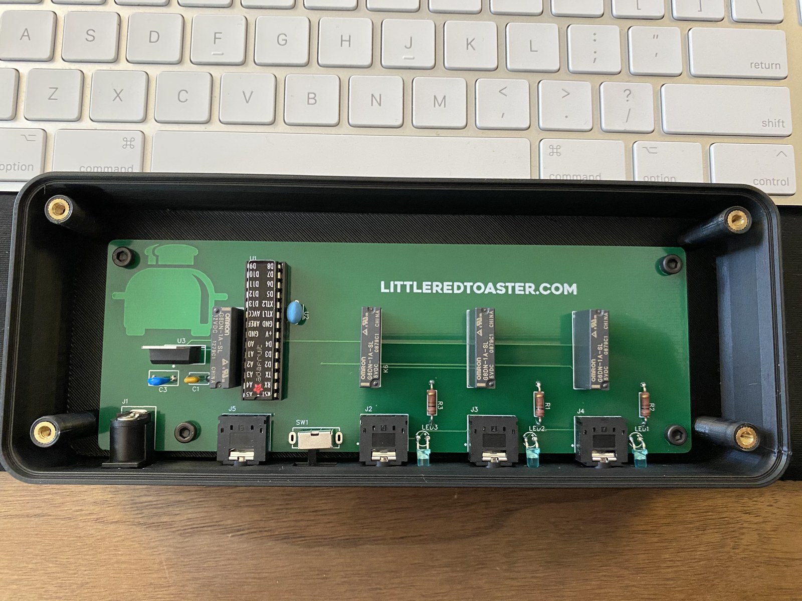
Most AV processors, and many receivers, have a 12V trigger output. When the processor turns on, the trigger goes to 12 volts, and anything wired to it, like a power amplifier, turns on with it. When the processor shuts off, the trigger drops and everything follows it down.
My processor had one trigger. I had more than one amp.
Not all at once
I also didn’t want every amp switching on at the same instant. Power amps pull a big rush of current when they first turn on, and several of them at once adds up. Turning them on at the same moment as the processor is also how you get pops and thumps through the speakers.
So the board does two jobs. A microcontroller watches the incoming trigger, and when it sees it, it turns the amps on in sequence instead of all together, and off the same way.
You can buy this. Emotiva’s ET-3+ trigger sequencer takes one 12V trigger and brings up to three devices on in sequence. I didn’t know it existed when I built mine.
The amp with no trigger input
One of my amps couldn’t follow a trigger at all. It’s a pro audio amplifier from Behringer, and it doesn’t have a 12V trigger input.
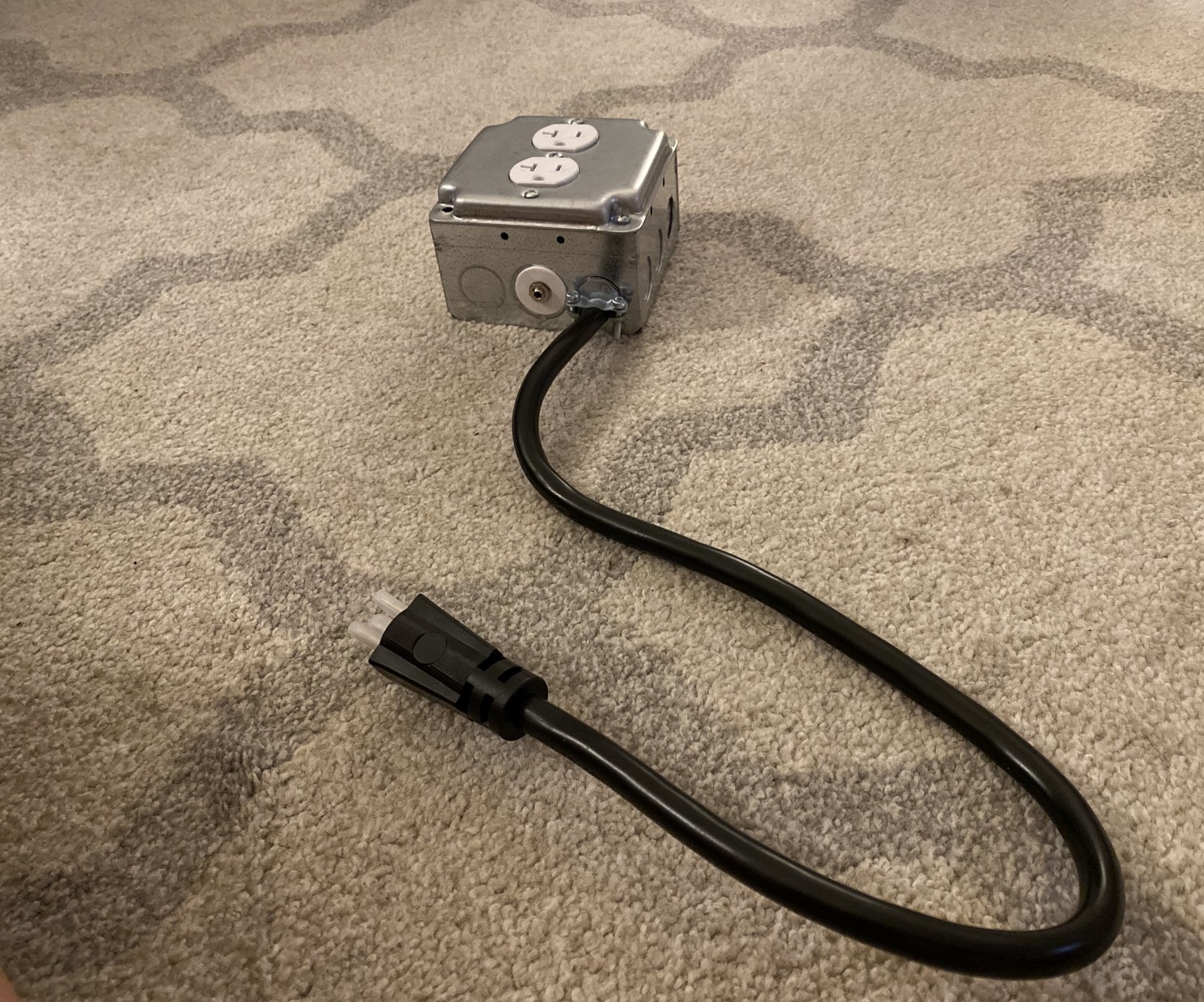
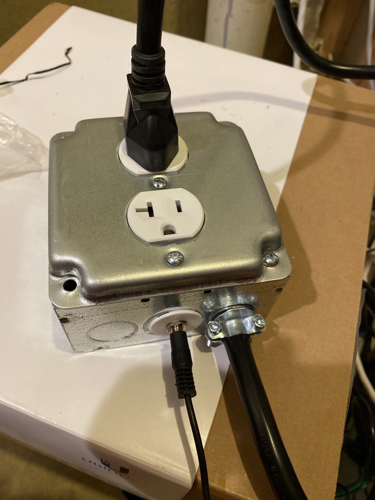
So in September 2020, before the board, I built it its own outlet: a metal junction box with a receptacle on top and a 120V relay inside that’s switched by 12V. When the trigger comes on, the relay turns the outlet on, and the amp powers up with it. It’s a DIY version of the Iot Relay, an enclosed power relay that switches its outlets from a low-voltage signal.
Breadboard to circuit board
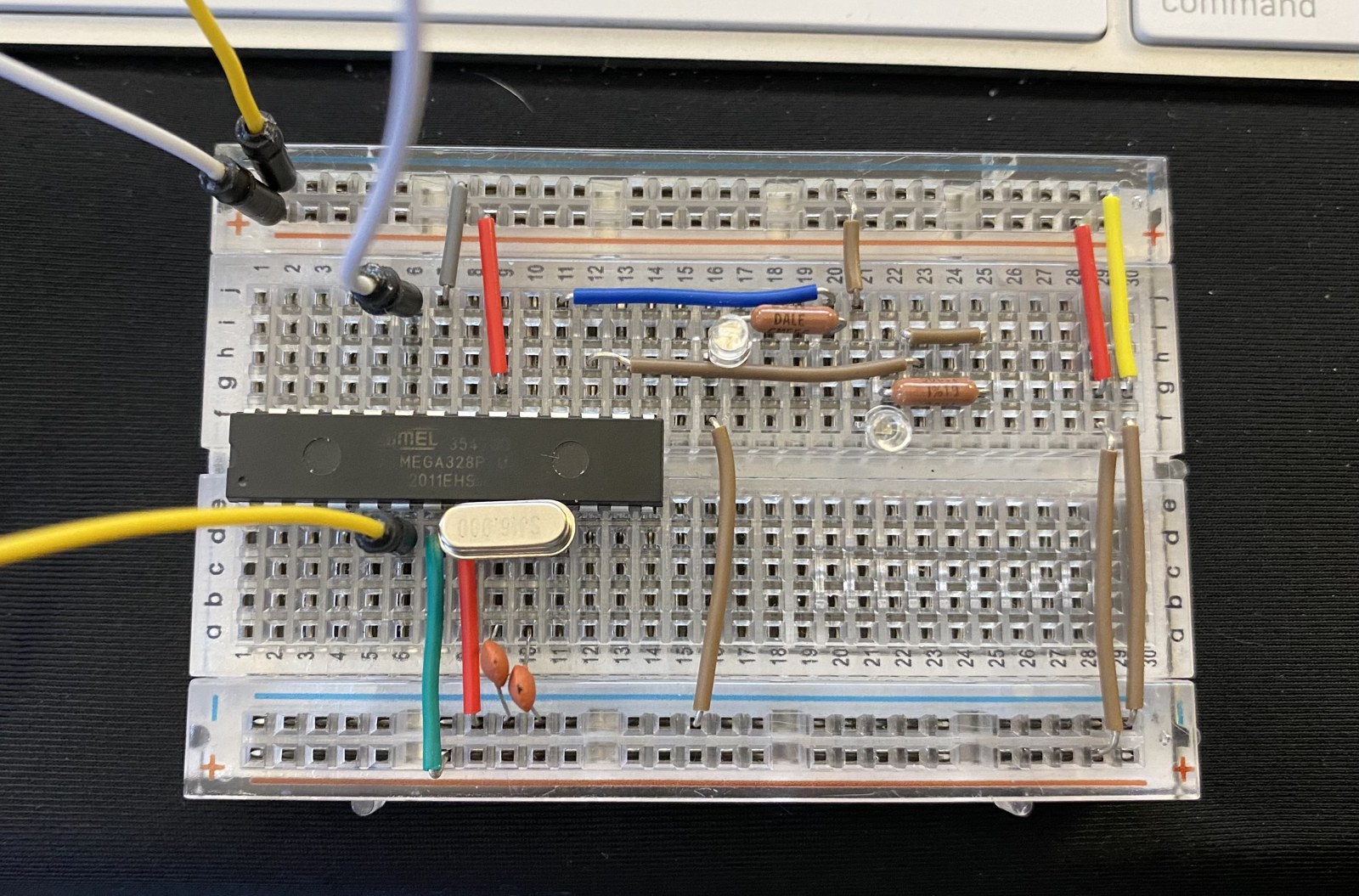
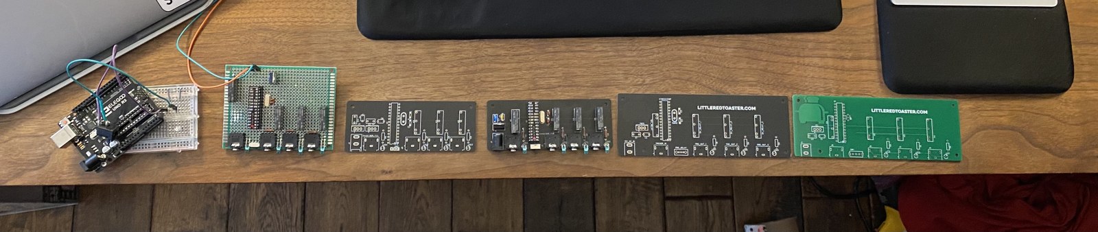
I started on a breadboard in November 2020.
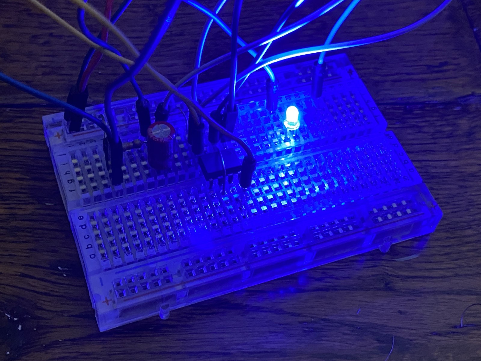
Next, the chip went on the breadboard by itself: an ATmega and its crystal.
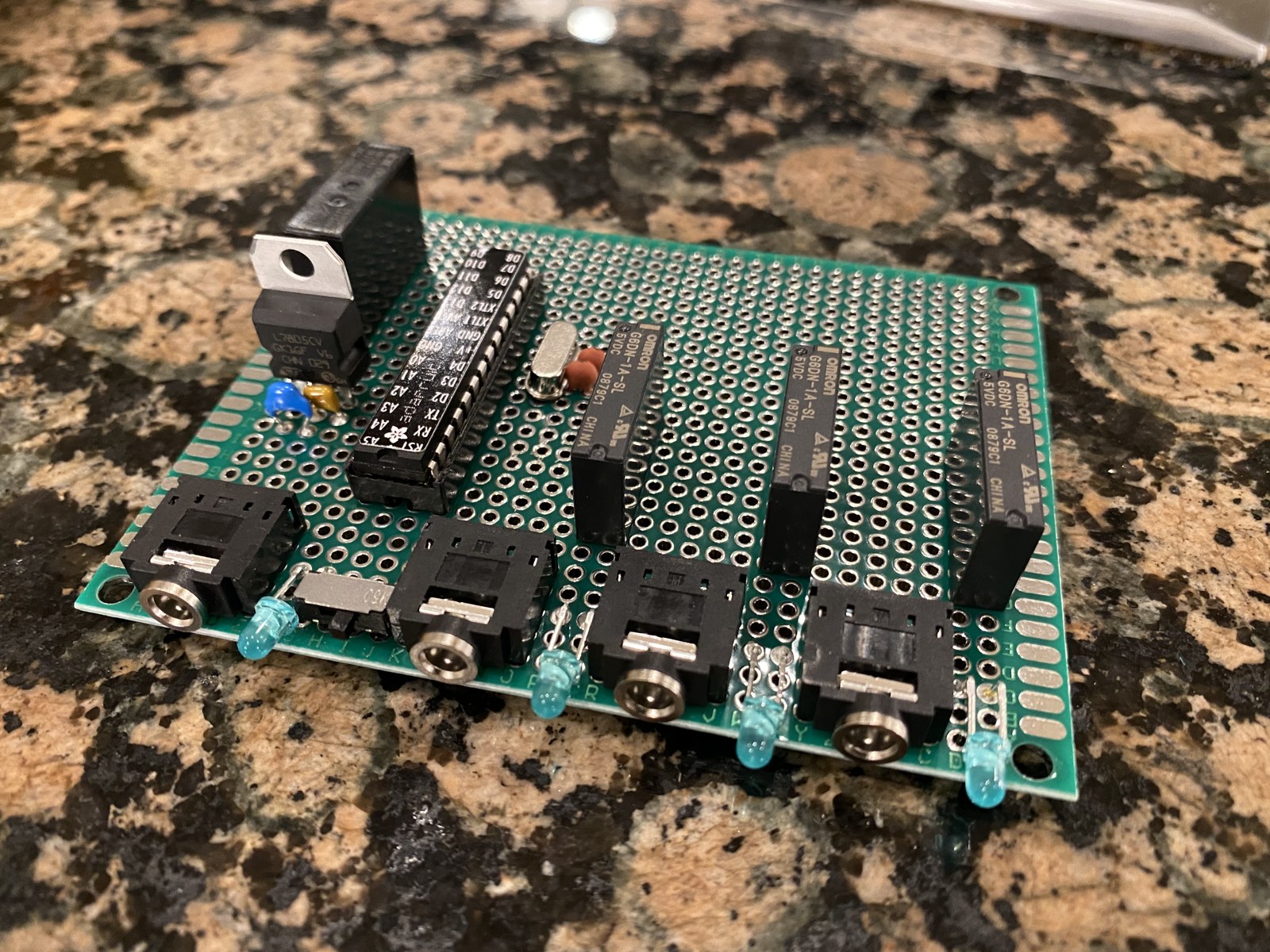
The next version was hand-wired on perfboard, with a power jack and a row of 3.5 mm jacks for the trigger cables.
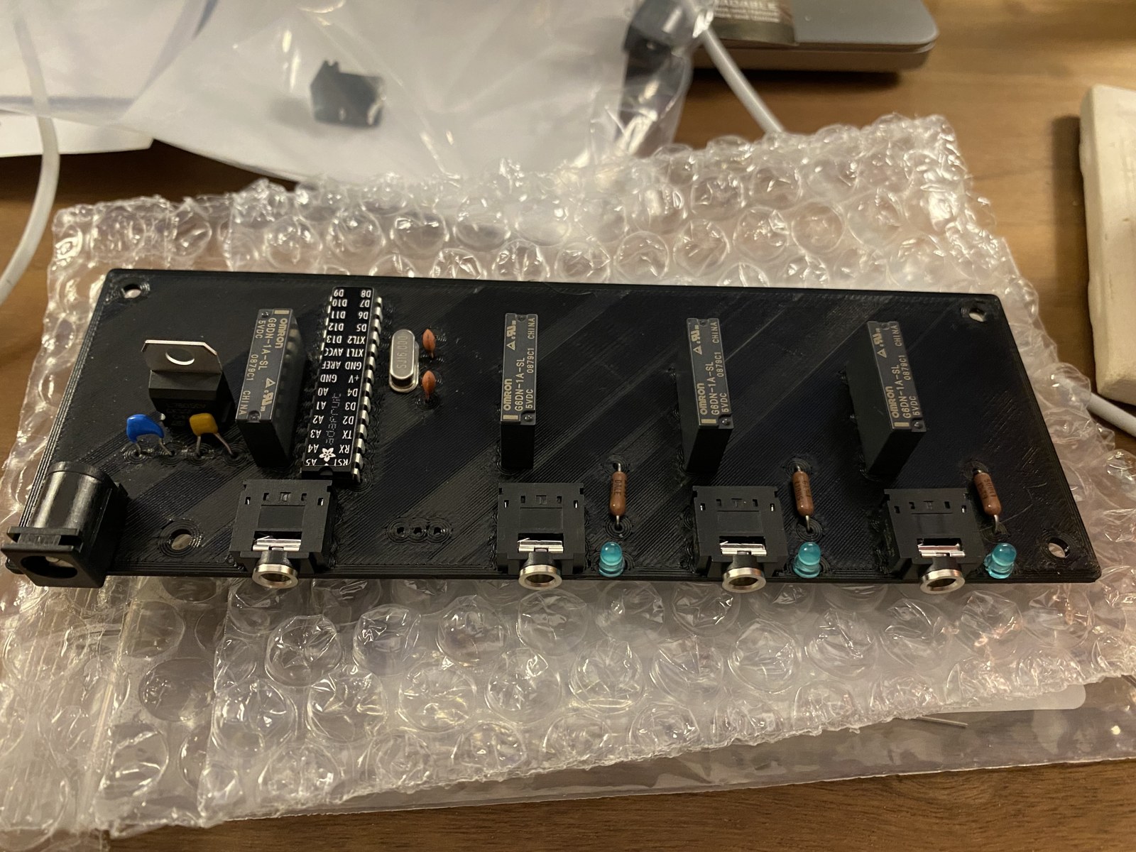
After that I ordered real circuit boards from JLCPCB. While I waited on them, I 3D-printed a model of the board so I could start designing the enclosure with something in hand.
The first boards took weeks to arrive, and then the chip wouldn’t boot. I’d mis-routed a ground connection. Once I’d spent a few hours figuring out what went wrong, the fix was quick. Then I waited another 2 to 3 weeks for the next round. It took three rounds of boards to get to the final one.
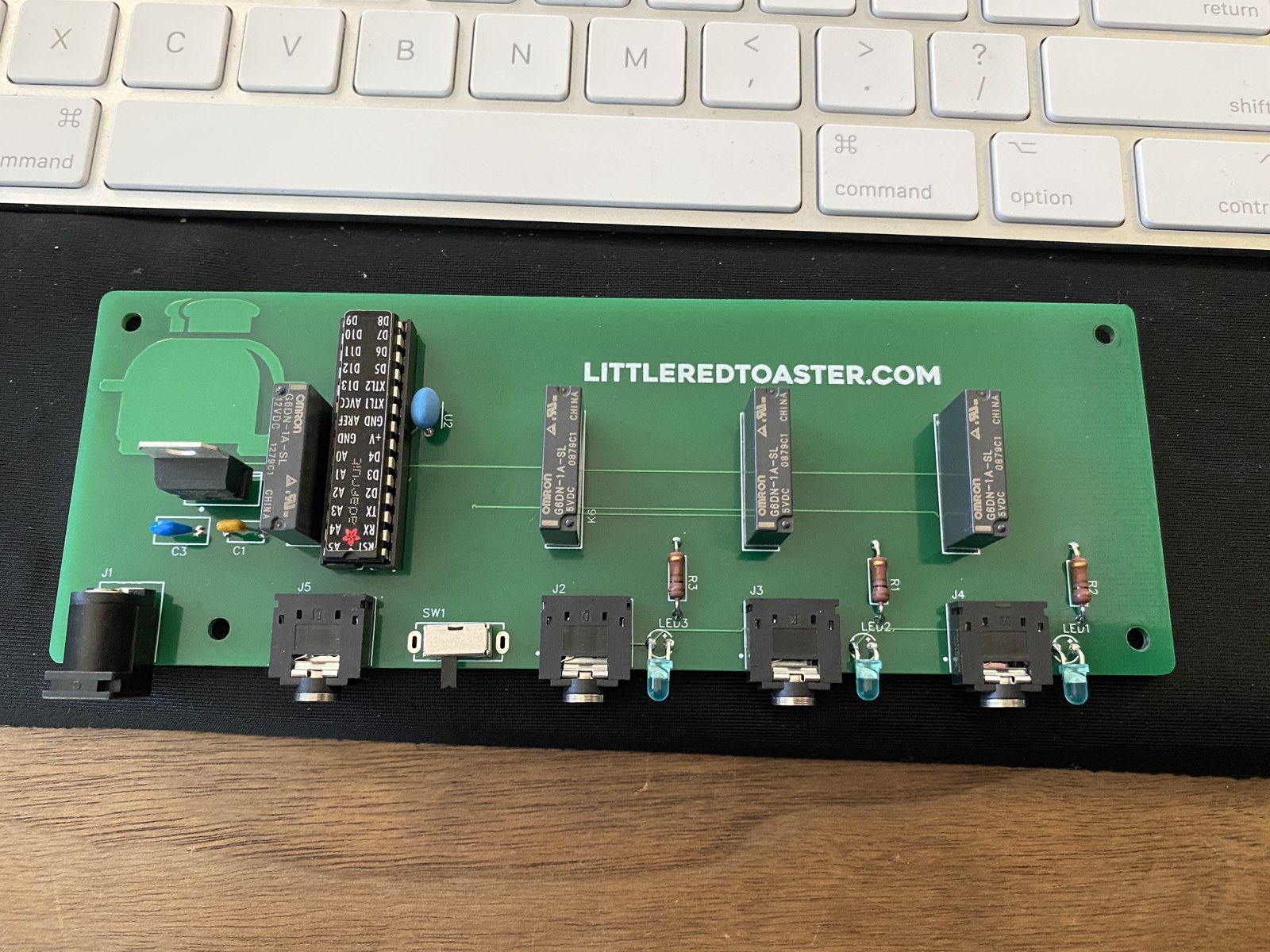
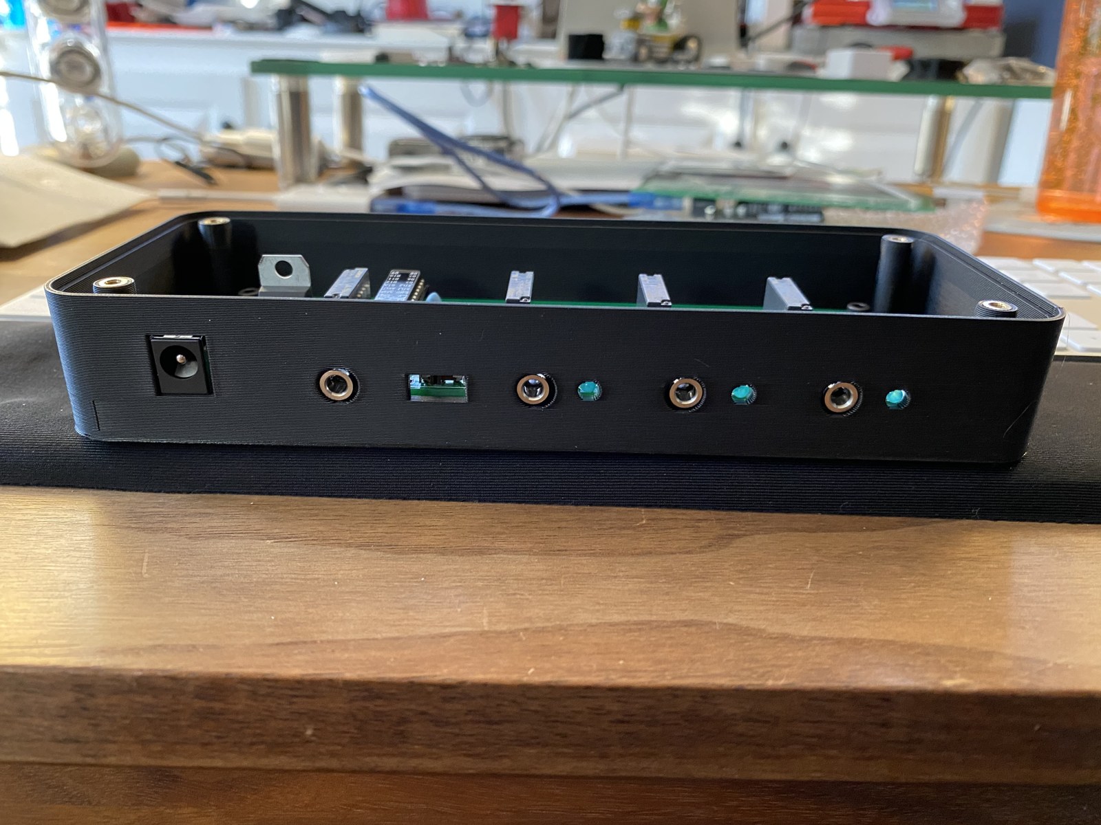
LittleRedToaster
The green board says LITTLEREDTOASTER.COM. That was my first business, before Emergent and Bright Wire, and it’s still running. I created and sell a custom harness that connects a Raspberry Pi to a Prusa i3 MK3/S/S+ 3D printer.
The plan was to sell this board there too. I never did. I didn’t have the time.
It’s still running in my theater.